Architectural mathematics for parametric design
Zlata Tošić is working as Researcher at the Geometric Modeling and Visualization (GMV) group at TU Dresden, Germany. Her PhD topic is the design of modular free-form shell structures for prefabrication by 3D concrete printing. Others fields of interest involve incorporating different geometry methods into parametric modeling tools for fabrication-oriented design approaches.
Aly Abdelmagid is a Ph.D. candidate at the National School of Architecture Paris-Malaquais (ENSAPM), University of PSL, France. He co-founded the Architectural Mathematics Group (AMG). His research focuses on geometry as an approach to morphological and constructive studies of complex structures in materials with low environmental impact.
Ahmed Elshafei has a Ph.D. in Mathematics (University of Porto 2022) and a Ph.D. in Architecture (University of Paris-Est 2014). His research in architecture focuses on the application of differential geometry in architectural design. He is currently a Post-Doc Researcher at CMAT (Centre of Mathematics, University of Minho).
Daniel Lordick studied architecture at the TU Berlin and the Carleton University in Ottawa. He holds a doctoral degree from the Karlsruhe Institute of Technology for a dissertation in the field of line geometry and is Professor at the TU Dresden, leading the research group Geometric Modeling and Visualization.
Keywords: differential geometry, parametric design, pre-rationalization, fabrication-oriented design
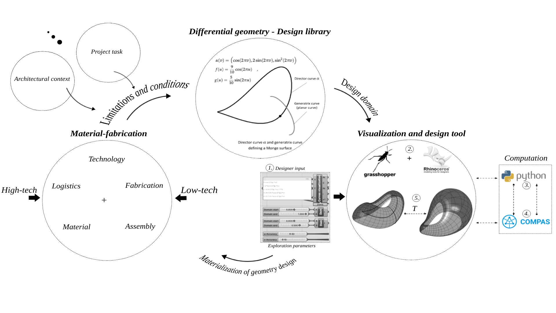
Fig. 1: Work-flow diagram of the proposed tri-nodal pre-rationalized approach.
Introduction
Despite the rapid advancement of technology, material development, and digitalization, architectural innovation still faces many difficulties, especially when it comes to the area of non-standard designs. We believe this is due to a lack of integrated design tools. The challenge arising from non-standard designs, in particular of doubly-curved shell structures, lies in their complex fabrication, especially within the context of sustainability and automation. To overcome this challenge, exploration of both high-tech and low-tech production solutions is needed. These solutions usually rely on specific characteristics, that influence design possibilities, making the process rather challenging for architects to readily create non-standard architecture. A brief look at the developments in the 1960s and 1970s can show that architecture embraced computer technology and programming, paving the way for what we now recognize as computational design. This shift had significant benefits, enabling architects to improve structural efficiency, reduce material usage, and construct larger and more ambitious structures. It also streamlined data formulation and exchange, enhancing project work-flows and reducing labour requirements. Moreover, structural analysis advanced as well, with efficient numerical methods and form-finding techniques, together with advancements in production and materials technology, progressing the construction industry in both efficiency and sustainability. Despite these advances, designing non-standard forms remained somehow challenging. It is true that CAD software packages, such as Non-Uniform Rational B-Splines (NURBS) 3D-modeling allowed the creation of more intricate shapes. However, the lack of understanding between geometry and fabrication resulted in them being costly, lacking construction efficiency, and often didn’t align with available technology. While these fields have traditionally evolved separately, recent interdisciplinary efforts have emerged to tackle architectural problems.
Rationalization in architectural design
In response the above-mentioned challenges, engineers developed two methodological approaches for the design of doubly-curved shell structures, which can be called post and pre- rationalization methods. Let us briefly explain the differences.
Post-rationalization
This method involves modifying already defined designs to fit within the constraints of fabrication and materials. While it provided a desired design form, it was often a tedious, expensive, and time-consuming process that led to compromises in form and potential tolerance issues due to geometric imprecision. On the other hand, its big advantage lies in its accessibility and the freedom it offers the designer in exploring a wide range of unconstrained shapes.
Pre-rationalization
This method approaches design by considering fabrication, technology, and materials as integral inputs from the outset. Its roots can be traced back to early 20th-century modernist movements championed by architects like; Le Corbusier, Walter Gropius, and the Bauhaus school.1,2 In the mid-20th century, builders like Frei Otto, Felix Candela, and Jorg Schlaich continued this trend, using various tools to establish the final shapes of their constructions.3,4 They prioritized factors such as structural efficiency, materials, construction techniques, form-finding, standardization, repetition, and sustainability. Fast forward to the present day, we observe the emergence of numerous design approaches that can be considered under the umbrella of pre-rationalization. Approaches comprising different form-finding options based on various construction and geometry methods.5,6,7,8 Let us briefly recall their categorization as follows.
(i) Geometrically-constrained: In this approach, we start with a mathematically defined shape of well-known fabrication properties. Since for such shapes the technological aspects are already taken into account, the design process is focused on the generation of various morphological solutions and their structural aspects. In this approach, the building materials’ relation to the chosen morphology is secondary.
(ii) Mechanically-constrained: In this approach, the shape is obtained as a solution to a mechanicalproblem. Here, the building material features predominantly in terms of its structural capacity, which eventually determines the morphological solution.
At the end, no matter which of the design approaches we pick, what could be retained from their comparison is that rationalization has to happen at some point in the design process in order for the shape / form / structure to be optimized to whichever constraint are deemed “constructible”. After evaluating these approaches, we do believe, however, that a common limitation among them is the absence of a comprehensive overview of the design possibilities when project conditions change, which can be referred to as the parametrization of the design. This leaves architects without a holistic framework to navigate the evolving landscape of their non-standard design. A second issue we observe is what can be referred to as the feasibility of the design, since they can be quite challenging for proper implementation. Finally, the above approaches, seem to be solutions for a particular problem whether in construction, production or material implementation. When going out of the bounds of these particular issues, the “solving algorithm” has to be changed. As a result, they cannot be used as a part of bigger design work-flow.
Our proposed approach
It revolves around the concept of pre-rationalization, but with a significant emphasis on building a design library rooted in a comprehensive understanding of the fabrication processes for doubly-curved structures, grounded in a deep knowledge of differential geometry. This approach enables us to exert precise control over a wide array of geometric properties, thereby enabling a broad spectrum of morphological solutions.
Differential geometry plays a pivotal role in this methodology as it allows us to categorize various types of surfaces and their parameterizations based on their geometric attributes, directly aligning with fabrication feasibility within different contexts. We achieve the manipulation of these forms through defined input parameters, which confine the “search” to specific domains where desired geometric properties remain intact.
Aside from the challenge of comprehending the differential geometry of these surfaces, another technical hurdle is translating these mathematical operations, which generate the surfaces, into a user-friendly tool for designers. We have developed a tool within the well-known Grasshopper plugin for Rhino, a platform that designers are more familiar with. This tool empowers designers to effortlessly generate shape variants of selected surfaces by adjusting specific input parameters that are carefully configured to maintain the necessary geometric properties for the fabrication process.
It’s worth noting that variations in shapes can arise not only from parameter adjustments but also from specific transformations that keep certain geometric properties invariant. This level of geometric control necessitates a meticulous analysis and classification of the underlying principles from differential geometry and their integration into the context of fabrication techniques.
Our approach inherently thrives on interdisciplinary collaboration. A parametrized model in Grasshopper establishes dynamic connections among geometry, architecture, computer programming, and fabrication / construction technologies. This interconnectedness facilitates a seamless flow of information throughout the analysis of the model, the planning of construction, and the production of intricate details such as element size, shape, curvature, and length.
To illustrate the proposed workflow, the next chapter introduces its implementation.
Proposed tri-nodal work-flow
Figure (1) describes the proposed work-flow that consists of three main disciplines that are tightly connected in a loop, these are:
| { | I. | Material-fabrication |
| II. | Differential geometry | |
| III. | Visualization and design tool |
I. Material-fabrication: In this node, the technology production with a used material needs to be defined with all the its properties. Together with the project tasks and architectural context, they represent limitations and conditions that have to be incorporated, satisfied by the design.
II. Differential geometry: In this node, the mathematical theory is explored and carefully formulated, giving rise to the geometric core foundation for the rationalized design library.9,10,11,12 The variants available in this library will always adhere to the assigned geometric properties needed for specific fabrication requirements. In more accurate terms, it is known that the kind of surface defining a (grid)shell and the type of its parameterization are crucial, as they are directly linked to the way the shell will be divided into discrete parts, such as panels, nodes, and beams.13,14,15 Hence, the choice of parameterization has a great impact on the fabrication of the discrete elements in question, as seen in the diagram:
Orthogonal patch ↔󠇟 Right-angled nodes
Conjugate patch ↔󠇟 Planar panels
Principal patch ↔󠇟 Developable beams
Similarly, the choice of the type of surface can be linked to certain mechanical properties that are usually seen in form-finding approaches. Therefore, it can be made to express a certain structural equilibrium (under constant normal loading) of the (grid)shell in question, for example:
Constant-Mean-Curvature surfaces ↔󠇟 Inflatable structures
Minimal surfaces ↔󠇟 Tensile structures
The combination of geometry and mechanics in (grid)shells, achieved by finding equilibrium in parameterized (membrane) shells offers architects and engineers diverse design freedoms. This integrated approach fosters continuous data exchange across three nodes, enabling nuanced decision-making. The first level entails choosing surface patches from a rationalized design library, driven by design aesthetics or project-specific factors like structure and construction requirements, given that different patch types may yield distinct shapes. These patches possess unique geometric properties and require various mathematical operations, some being straightforward with explicit coordinate equations, while others involve more intricate mathematical derivations and subsequent translation into parametric modelling tools like Grasshopper.
III. Visualisation and design tool
In this node, a lot of the emphasis is on the construction of an accessible interface for designers to be able to generate geometrically consistent design variants from the rationalized design library. This is achieved, by the translation of the mathematical theory from literature, through computer coding language into objects that could be visualized and manipulated through a list of parameters within the CAD interface (Rhino + Grasshopper). This is done through three steps of data flow linking the CAD interface and an external framework.
– Step 1: The mathematical expressions and domains that define the surface patch and its limits are fed into the CAD interface.
– Step 2: The input data is then calculated within the external framework using necessary mathematical operations that are written in Python and Compas framework.16
– Step 3: The calculated data is returned to the CAD interface as point coordinates from which the surface is constructed and visualized.
A continuous surface facilitates exploration of its geometric properties, aligning them with building materials’ physical and mechanical traits. Our goal is to provide designers with extensive input parameters for maximum shape versatility, primarily through carefully executed surface transformations. These transformations maintain the surface’s geometric properties while potentially enhancing shape complexity. Presenting solutions as Grasshopper components streamlines user interaction, focusing solely on input parameter adjustments, and eliminating complexities. Results reintegrate the rationalized shape into Grasshopper, enabling comprehensive coverage of construction analysis, element specification, and materialization. This includes specifying structural elements like nodes, rods, panels, or blocks within the chosen rationalized shape, considering fabrication, logistics, assembly processes, and connections. The parametric nature of the shape allows easy manipulation through its parameters to accommodate element requirements. In summary, we aim to provide designers with a wide range of input parameters to maximize shape variation through surface transformations. This user-friendly approach in Grasshopper simplifies the design process and results can be integrated seamlessly into construction analysis, element definition, and materialization. The parametric nature of the shape enables easy adjustments to meet specific element requirements.
Conclusion
This approach allows for the integration of other disciplinary fields within the process. The number of the research fields is not fixed, but more open to the addition of any new ones that prove important in the formulation of the rationalized design process. In this manner, the future work will hopefully go in the direction of incorporating other factors, such as structural efficiency, as well as art and material sciences. Moreover, the shape variations can be used to optimize the structural performance and material consumption, more precisely by comparing them through an “optimization matrix” and arriving at an “optimal” shape (within the designated family) in terms of fabrication. Note that additional factors can also be prioritized in relation to the particularity of each project, extracting potential solutions for non-standard architectural morphologies, enabling the implementation of research across multiple fields simultaneously. Finally we would like to say that our aim is to further develop the pre-rationalized work-flow by linking the rationalized design library with other fields, such as physics and engineering, facilitating the implementation of concepts from these fields through the differential geometric rules.
Acknowledgements
The research of the first author is part of the priority program SPP 2187: Adaptive Modular Construction with Flow Production Methods – Precision High-Speed Construction of the Future in the subproject Formwork-free Flow Production of Adaptive Supporting Structures from Variable Frame Elements – Adaptive Concrete Diamond Construction (ACDC) funded by the German Research Foundation (DFG). The research of the third author Elshafei, A. was partially financed by Portuguese Funds through FCT (Fundao para a Ciłncia e a Tecnologia) within the Projects UIDB/00013/2020 and UIDP/00013/2020.
References
- Le Corbusier. 1963. Towards a New Architecture. London: Architectural Press. ↩︎
- Isaacs, R. R. 1991. Gropius: An Illustrated Biography of the Creator of the Bauhaus. 1st English-language ed. Boston: Little, Brown. ↩︎
- Schlaich, J. 1940. “Leichtbau – eine Forderung unserer Zeit.” Bautechnik 90(213): 12. ↩︎
- Otto, F. 2015. Finding Form, 1925–2015. Jens Harzer spricht Frei Otto. Cherbuliez Productions GbR. http://www.processform.de/projekte/graphic-design/frei-otto-finding-form-1925-2015-jens-harzer-spricht-frei-otto-cherbuliez-productions ↩︎
- Block, P., and J. Ochsendorf. 2007. “Thrust Network Analysis: A New Methodology for Three-Dimensional Equilibrium.” Journal of the International Association for Shell and Spatial Structures 48(155). ↩︎
- Collins, M., and T. Cosgrove. 2019. “Dynamic Relaxation Modeling of Braced Bending Active Gridshells with Rectangular Sections.” Engineering Structures187: 16–24. https://doi.org/10.1016/j.engstruct.2019.02.001 ↩︎
- Cutler, B., and E. Whiting. 2007. “Constrained Planar Remeshing for Architecture.” Proceedings of Graphics Interface 2007 (GI ’07): 11. https://doi.org/10.1145/1268517.1268522 ↩︎
- Deuss, M., A. H. Deleuran, S. Bouaziz, B. Deng, D. Piker, and M. Pauly. 2015. “ShapeOp—A Robust and Extensible Geometric Modelling Paradigm.” In Modelling Behaviour, 505–515. Springer International Publishing. https://doi.org/10.1007/978-3-319-24208-8_42 ↩︎
- Eisenhart, L. 1909. A Treatise on Differential Geometry of Curves and Surfaces. Boston: Ginn and Company. ↩︎
- Eisenhart, L. P. 1923. Transformations of Surfaces. Princeton: Princeton University Press. ↩︎
- DoCarmo, M. 1976. Differential Geometry of Curves and Surfaces. Englewood Cliffs, New Jersey: Prentice-Hall, Inc. ↩︎
- Gray, A., E. Abbena, and S. Salamon. 2006. Modern Differential Geometry of Curves and Surfaces with Mathematica. Third Edition. Chapman & Hall / CRC. ↩︎
- Bobenko, A., and Y. Suris. 2005. Discrete Differential Geometry: Consistency as Integrability. Available from arXiv:math/0504358. ↩︎
- Liu, Y., H. Pottmann, J. Wallner, Y. Yang, and W. Wang. 2006. “Geometric Modeling with Conical Meshes and Developable Surfaces.” ACM Transactions on Graphics (Proc. SIGGRAPH) 25(3): 681–689. ↩︎
- Pottmann, H., A. Schiftner, P. Bo, H. Schmiedhofer, W. Wang, N. Baldassini, and J. Wallner. 2008. “Freeform Surfaces from Single Curved Panels.” ACM Transactions 27(3): 1–10. ↩︎
- Van Mele, Tom, et al. “COMPAS: A Framework for Computational Research in Architecture and Structures.” Accessed 2021. http://compas.dev. ↩︎